YC156 Conversion
![]()
This
particular amplifier project started almost thirty years ago. Around 1973, the
original chassis was modified to use a 4CX1000A. The YC156 triode is the third
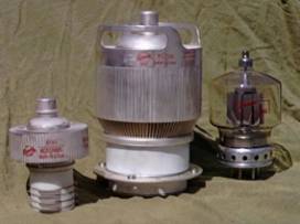
tube type to be used in this chassis. Why? Well, I was always unhappy with the
4CX1000A, and, I always wanted a tube with handles! This photo might show you
why. That's a 4CX1000A, a YC156, and a 4-400A for comparison.
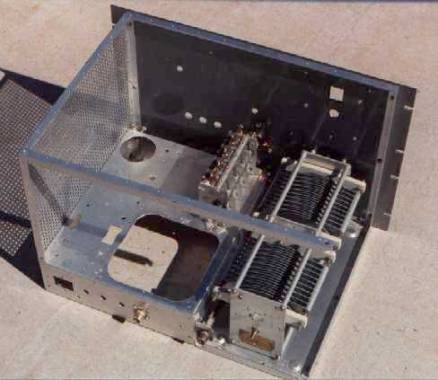
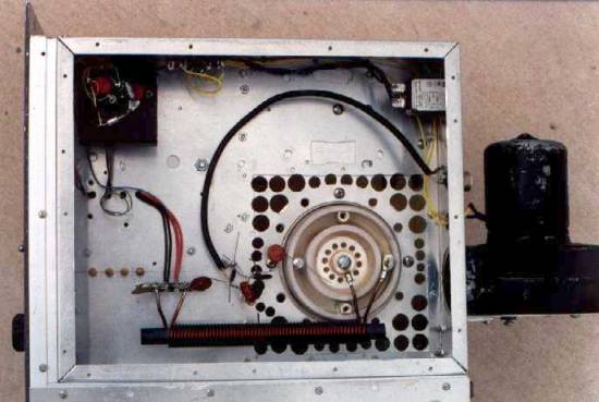
The
following photos show the progress as I stepped through the conversion. This
one shows the chassis after all the 4CX1000A parts have been stripped off. The
large hole just behind the load capacitor was where I mounted the modularized
tube socket and associated components. This approach made it easier to change
tube types.
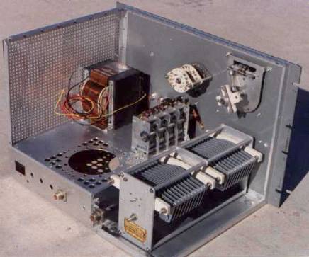
This next
photo shows a new aluminum plate installed for the YC156 to mount to. This tube
bolts right to the chassis, no socket to mess with. The small holes are for air
flow from the lower pressurized compartment to the tube anode. Also shown are
the filament transformer, the turns counter for the roller coil, and what
passes for a band switch.
The
hardest part of this project was dealing with the sheer physical size of this
tube. There was no room for the proper chimney to mount, so I had to improvise.
G10 fiberglass-epoxy board was used to fabricate a square box. The square shape
was necessary because of the limited space. The plate choke consists of #26
wire close wound for 4 inches on a 1 inch diameter G10 form. The wire ends are
held in place with Scotch #27 tape. The whole thing was given several coats of
MIN-WAX exterior urethane spar varnish.
This one
shows the bottom of the chassis. An EMI filter on the AC line is in the upper right.
The bias circuit is in the upper left corner. A temporary cathode pi-net for 40
meters is dangling on the end of the coax. This will be replaced with a
multi-band board later. The blower is small. Much smaller then I would like. However,
if I can believe the Eimac data sheet and my manometer, I can dissipate 1800
watts continously at 50 degrees ambient temperature and not exceed any seal max
temperatures. More than enough for 1500 watts out. HI!
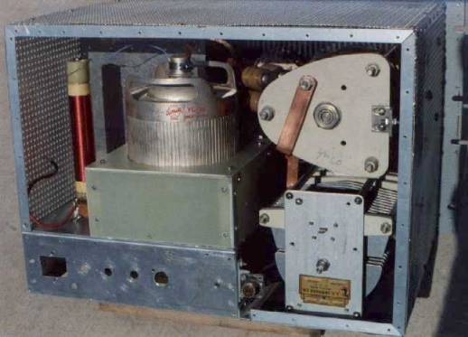
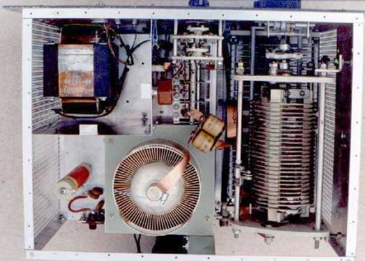
Here is a
top view of the business end. The roller coil is all ceramic insulation with
multiple rollers for the tap point. I have not had any contact arcing or localized
heating, so far. A roller coil would not be my first choice for a serious
amplifier, but in this case, it's a good deal. I plan to experiment with
different tube operating conditions and the roller coil will allow me to change
match impedance and Q without re-winding the coil. The "bandswitch"
is small because all it has to do is select the correct cathode network relay
and loading cap padder. The anode DC blocking cap is made from four TV type
20kv 500 pf, ceramics. These work pretty good as coupling caps, but not so good
as tank components. All tank interconnects are made from 1/2 inch copper strap.
Most of the connections are made with copper or brass bolts and nuts, although
a few had to be soldered.
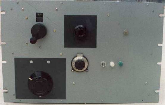
And
finally, the front panel. The layout was determined by the location of holes
used in the past. The dark areas are painted aluminum plates covering up excess
holes. If I ever finish this experiment, I might fill the extra holes with
Bondo and repaint. Since this project has been ongoing for all these years, I
doubt if I'll live long enough to have to worry about that!
![]()